A standalone amplifier based on the QRP Labs 10 W amplifier module
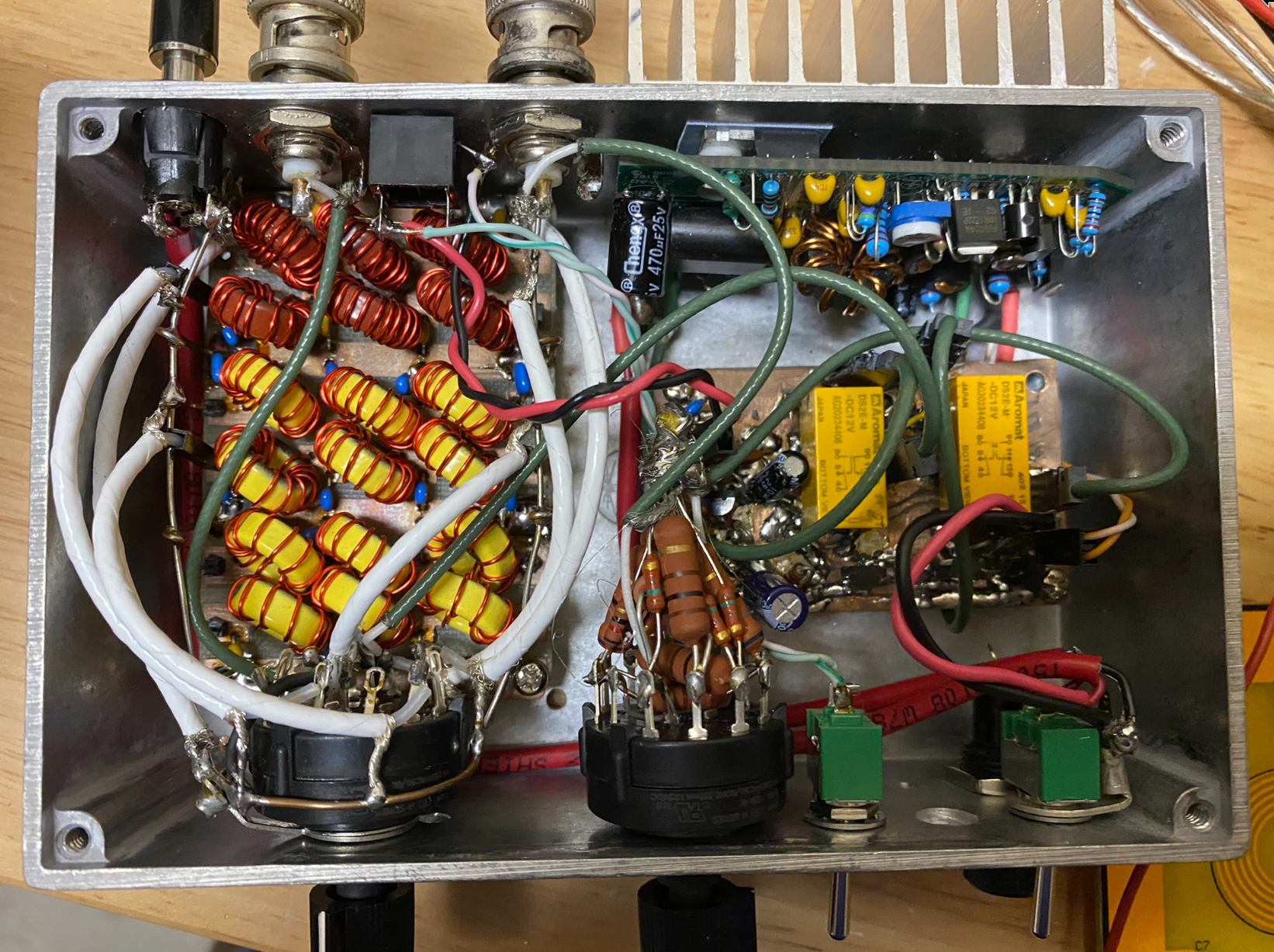
The somewhat scary wiring in the completed 10 watt amplifier project. See limitations below.
When building small transmitters, sometimes you want a little more power so you can QSO a little more effectively. The project described here is a compact wideband 10 watt amplifier for HF based on the QRP Labs 10W amplifier module. In order to have a standalone amplifier usable directly with a transceiver, this module also needs a transmit/receive switch and low-pass filtering at the output. These are all integrated into this box. I started on this project in summer 2021 and didn't finish until spring 2022.
The 10 W amplifier module
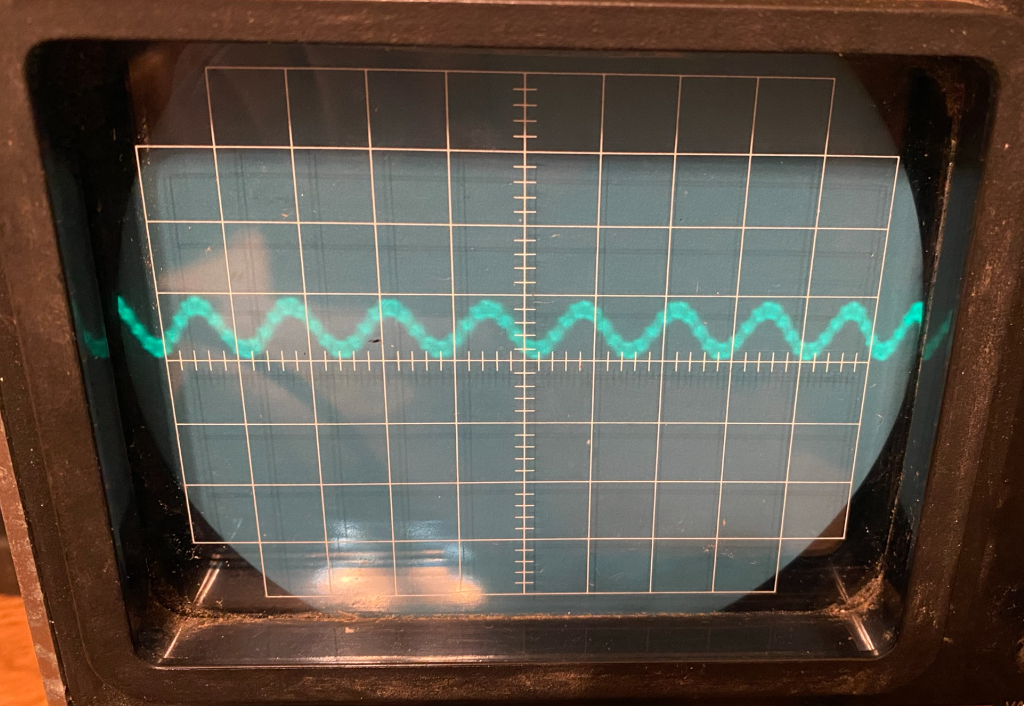
Before fixing a mistake with T203, parasitic oscillations were visible even on a 15 MHz scope.
QRP Labs sells a compact, inexpensive 10 Watt amplifier module that was the basis for this project. I built this in a day in summer 2021. Because of a mistake I made, its output was severely distorted, with parasitic oscillations. I did not make any QSOs with it at this point in time. At the time, I suspected one of the BS170 driver transistors might be shorted. MOSFETs have a very thin gate insulation which can easily be punctured by static electricity, and this happened to me when I was building the Softrock RXTX transceiver earlier that year.
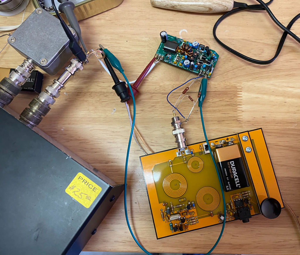
After fixing the mistake with T203, I tested the amplifier with a Cricket 40. I forgot the heatsink in this picture. I did not key down for too long so the amplifier was OK, but this is not recommended.
However, after probing around, burning some of the 2.2 ohm drain resistors on Q203 and Q204, and rereading the schematic, I found I had connected T203 incorrectly. The direction of windings on this transformer is critical and cannot be reversed. The manual documents this properly, I just didn't read it carefully enough at the time! With this change and after replacing all the burnt parts, the amplifier was putting out a clean signal of about 8 watts with a low pass filter on the output.
Input attenuator
Since the gain of the PA unit is fixed, I built a bank of pi attenuators on a rotary switch to attenuate the input to the amplifier to provide the desired power out. Though the input impedance of the PA unit is not 50 Ω, this works well enough. Unfortunately, this method of construction looks very messy, but it works well and I can switch between 6 attenuators.
Transmit/receive switching
A T/R switch in the same box allows bypassing the amplifier on receive, and switching the amplifier between the rig and antenna port on transmit. This switch also takes care of the /TX input to the amplifier, which is to be grounded on transmit.
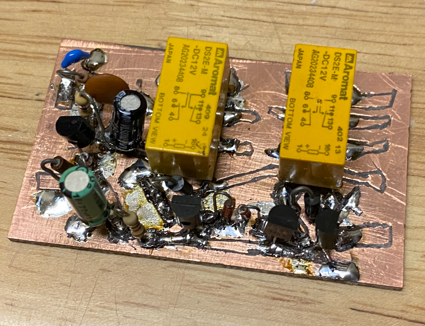
The incomplete second version of the T/R switch including traces cut with a knife.
I originally built a T/R switch on a scrap piece of copper-clad board, but this was too messy for final use. I rebuilt the T/R switch on a new board in spring 2022. It takes the same 12 volt supply as the actual PA unit.
The T/R switch itself consists of two relays which are driven by relay drivers described in the W1FB Design Notebook. There is some other circuitry around that, for example, for the /TX input to the PA unit.
After building the first and second versions of this T/R switch, I found I hadn't planned things out as well as I should have. Eventually, I had to add some connectors between the two relays, and this was difficult. These connectors were for coax for the actual RF, power connections, and the /TX line. Next time, it might be easier to install the relays last or "dead bug style."
I have a schematic of this switch in a notebook, but need to find it.
Low-pass filtering
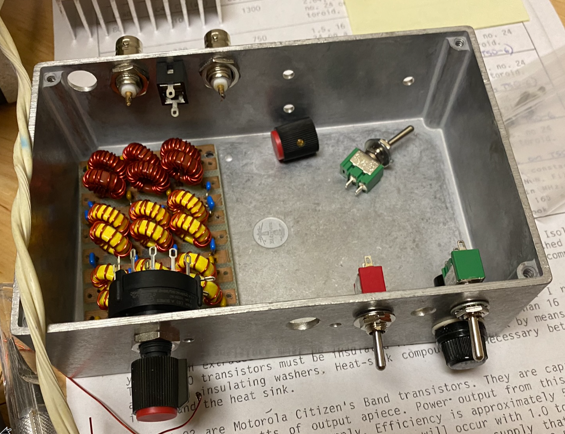
The low-pass filter board barely fit in the Hammond 1590J enclosure with the switches and RF connectors.
My plan for low-pass filtering at the output of the amplifier was a bank of low-pass filters using values by W3NQN. I built filters for the 6 bands provided in the table, and planned to use a rotary switch for changing bands. The filters themselves worked fine, and I mounted them on a board that I had CNC milled at Texas InventionWorks at UT Austin. I drilled the holes for components at home using an oversized drill bit and mounted everything in standard through-hole style. However, this board just barely fit in the box with the amplifier and T/R switch boards installed, leaving very little space for the rotary switch.
I managed to get the 6-position rotary switch to fit in the box, but could not route the coax effectively without putting too much strain on the rotary switch pins. Eventually, I just connected filters for 40 and 20 meters and left the rest alone. In the future, it would likely be worth it to remove this entire board and move it to a box of sufficient size to switch between all the filters properly.
Putting it all in a box
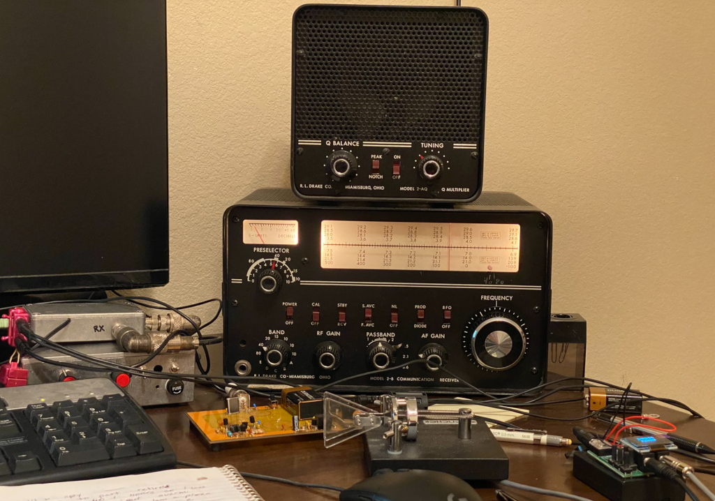
Making some QSOs with a Drake 2-B, Cricket 40, and an external homebrew T/R switch.
For this project I managed to fit everything in a Hammond 1590J enclosure. Some coax was especially difficult to route, but the amplifier worked in the end and was used in some QSOs with a Cricket 40 as a transmitter and Drake 2-B as a receiver. Unfortunately, because of the haphazard routing of wire and coax, and the strain placed on connectors, it is still a little scary. The coax used had a stranded core but was more rigid than desired due to a Teflon? jacket.
Special thanks
I couldn't have done this year-long project or learned so much alone, and would like to thank my elmers in the Austin QRP Club — Kees K5BCQ, Darrel WA7OIB, and many others — for supplying parts, guidance, and advice. Thanks y'all!
References
[QRPLabs] QRP Labs, 10W HF Linear PA, 2018. Available online.
[W1FB] Doug DeMaw, W1FB's Design Notebook, 1990, p. 44.
[W3NQN] Doug DeMaw, W1FB's Design Notebook, 1990, pp. 159-160.
[TIW] Texas InventionWorks. Available online.