The Michigan Mighty Mite

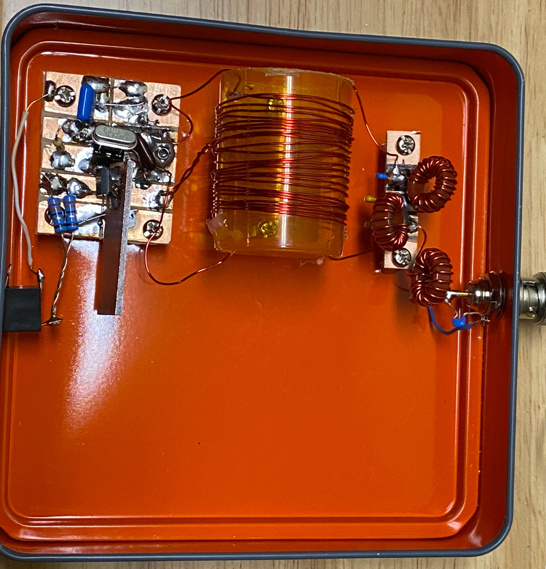
My attempt at a MMM transmitter, showing the board on the left, the transformer in the center, and low pass filter on the right.
The Michigan Mighty Mite [K4TWJ, KC6WDK] is a very simple QRPp transmitter built from junk-box parts.
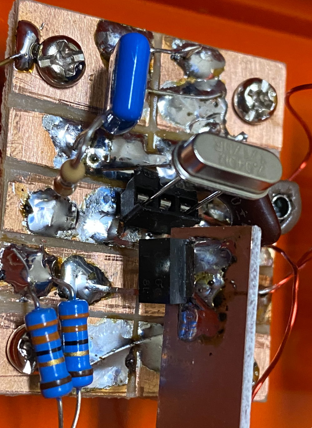
I built the circuit using the schematic provided by KC6WDK. I used a 2SC5706 transistor I had lying around, and a parallel combination of 33 and 100 ohms for the emitter resistor for Q1. (I did not have a 27 ohm resistor.) The coil was wound on an old pill bottle. The circuit was built on a small piece of scrap single-sided PCB stock, and I used a hacksaw to cut isolated pads on the board. K0IYE writes that these traces can be effectively carved out of the PCB stock using a wood gouge. I will have to try that for my next project.
I added a 7-element low-pass filter at the secondary of the transformer to provide some harmonic attenuation. The 365 pF variable capacitor was replaced with a 30 pF fixed capacitor in parallel with a 80 pF trimmer. This seemed to be enough. I tried 100 pF and 180 pF in parallel with the trimmer first, but they gave the best output at the lowest setting of the trimmer.
Difficulties
(Note that the author is new to building, so many newbie mistakes were made, and some are documented here.)
- Crystals overheating. I had originally put two 33 ohm resistors in parallel for the emitter resistor, but this made the crystal get very hot and unstable. Increasing the resistance to about 25 ohms helped prevent this problem.
- Decreased output power. I'm measuring about 300 mW of output from the transmitter into 50 ohms. This is almost "close enough" to the advertised 500 mW, but even with the 25 ohm emitter resistor, the crystal is getting a bit warm. This is a work in progress...
- 200Hz or more of chirp. I think this is caused by the overheating crystal. I was able to decrease chirp significantly by moving all the windings of L1 and L2 closer together. See below. There is still a large amount of drift at the beginning, but it might actually be usable on the air now after the oscillator "warms up"!
- Windings and connections of L1. It is not clear from KC6WDK's web page how the primary winding L1 should be connected, since the tap is not in the middle. Several pictures online [W2AEW, QRPGuys] hint that the end of L1 closer to the collector tap goes to the +12V line, whereas the other end goes to the crystal.
- Direction of L2 winding. KC6WDK's web page indicates that L2 must be wound in the same direction as L1. I'm not sure why it would be needed to do both windings in the same direction. If the winding was in the opposite direction, it should provide a 180 degree phase shift of the signal on the secondary with respect to the signal on the primary. That should not cause any problems because the transformer is only used for output coupling and not for feedback. Some local elmers answered that it should not make a difference.
- Closeness of windings of L1 and L2. W2AEW's MMM transmitter has very neatly wound L1 and L2 inductors. Mine had windings spaced all over the coil form. I pushed these all to the center (i.e. increased the inductance of both windings), and the output waveform became much cleaner at any setting of the variable capacitor.
Conclusion
Because of chirp and overdriving crystals, I haven't yet been able to put the Michigan Mighty Mite on the air. Perhaps decreasing the amount of feedback will help. This is still a work in progress, but for now I've put it aside and will work on other projects.
References
[K4TWJ] Dave Ingram, "World of Ideas: QRP Fun, Part II." CQ, Vol. 48, No. 3, Mar. 1992, pp. 107-108.
[KC6WDK] George Rosenberg, "500 mW CW Transmitter." Available online.
[QRPGuys] QRP Guys, "MMM+ 40m Transmitter." Available online.
[W2AEW] Alan Wolke, "Playing with a Michigan Mighty Mite tonight, joining the Color-burst Liberation Army. @soldersmoke." Twitter, Jan. 24, 2016. Available online.
[TIW] Texas InventionWorks. Available online.
